Generating CAD with AI-Written Python
Could AI-written CAD code give me the dimensional control I wanted for 3D printing and CNC?
A cigar ashtray and whisky glass holder, modeled with AI-written build123d Python and taken through STL import, toolpaths, and CAM simulation.
I wanted to make a cigar ashtray with a whisky glass holder. I'd already tried text-to-3D mesh generators and liked what they could do for general shapes, but detailed sizing requirements were harder to work with. This time I had AI write Python using build123d. I was surprised by how easily it produced both an STL and the top-down SVGs I needed for my CNC workflow.
Giving the design dimensions
The object is fairly simple to describe: a tray with a place for a glass, an ash bowl beside it, and cigar rests across the bowl's rim. The model has rounded corners and edges, two opposed cigar cradles, and a separate removable liner.
Those features also have relationships that matter. The pockets need to fit inside the body. Their depths need to leave material underneath. The liner needs clearance inside the bowl. A model can look convincing while still getting those details wrong.
The generated code made those relationships visible. In the VS Code screenshot, the model starts with build_whiskey_tray(d=Dimensions()). The body, glass pocket, bowl, and edge fillets are built from named dimensions. There are also assertions checking relationships between the pocket depths, body height, and available space.
That gave me something concrete to inspect alongside the preview. I could look at how a pocket was constructed or where an offset came from. A dimension in the source is an explicit input I can change and regenerate. It still needs checking, but I can see what the design is asking for.
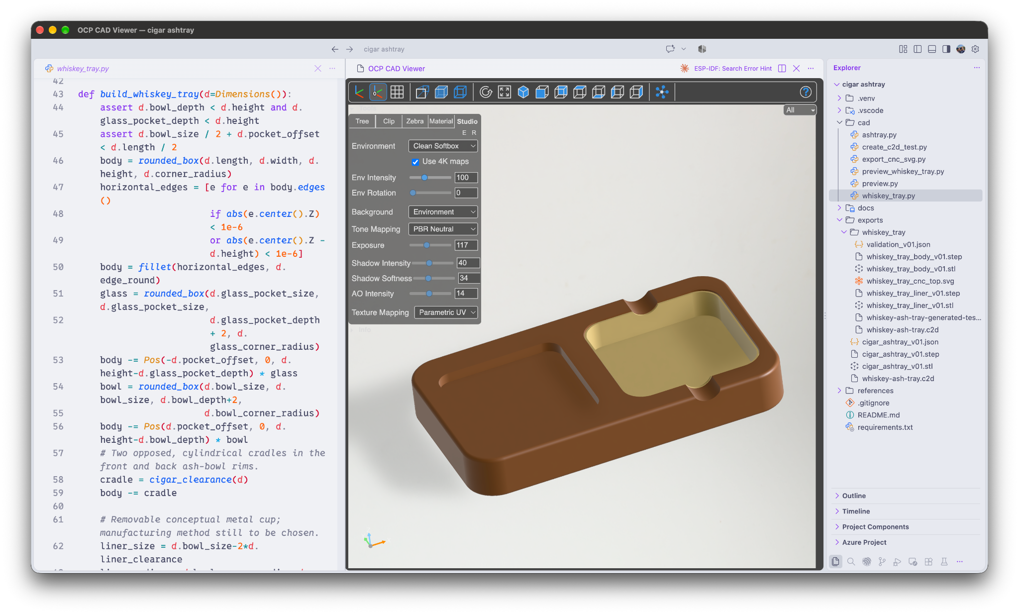
The Python source, CAD preview, and export folder together in VS Code. The gold part represents a conceptual removable metal liner.
One design, several outputs
Getting a model on screen was only part of what I wanted. I needed files that could move into the tools I already use.
The export folder contains separate body and liner files in STL and STEP, along with whiskey_tray_cnc_top.svg. The STL provides a mesh for a 3D-printing slicer or a CAM workflow that accepts a 3D model. The top-down SVG provides 2D profiles for CNC work.
Those outputs carry different information. The SVG is useful for outlines and profiles; it doesn't contain the complete machining setup or explain how deep to cut each feature. The 3D mesh carries the surface shape. Tool selection, cutting depths, machining strategy, and setup still belong in CAM.
The useful discovery for me was that AI-written CAD code could produce these different views of the same design. The result fit into an existing workflow with familiar file formats.
Taking it into Carbide Create
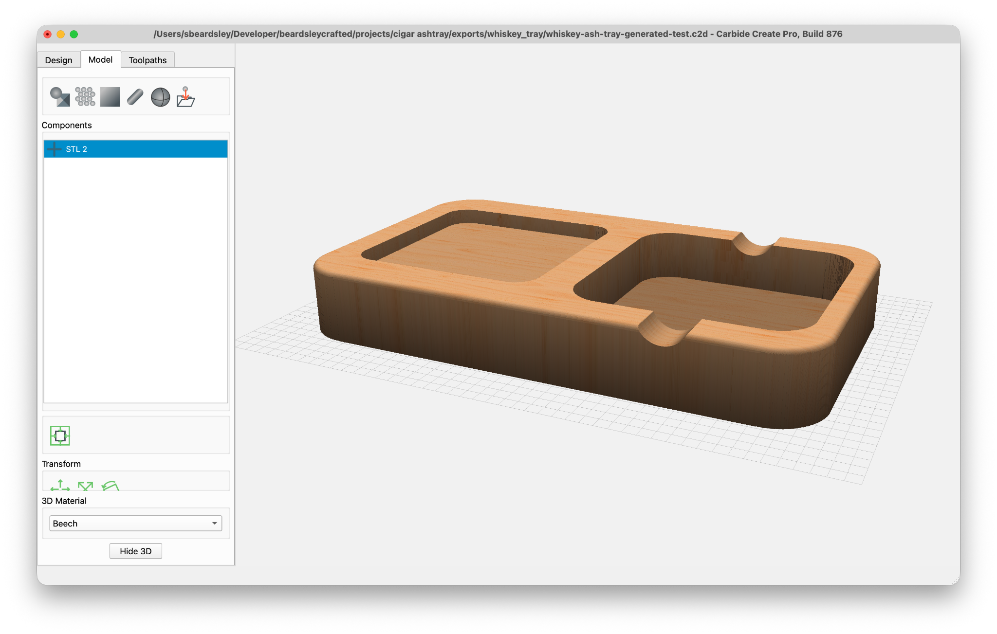
I brought the STL into Carbide Create, my CAM software. The imported component appears as STL 2, with the glass pocket, bowl, rounded body, and cigar rests visible in the model view.
The STL-based CAM model. The wood appearance here is a software preview.
From there, the CAM project includes 3D roughing, 3D finishing, and a cutout operation. The top-down toolpath view shows the passes across the model and around its perimeter. This is the STL-based machining path shown in the screenshots; the separate SVG export offers the 2D geometry route.
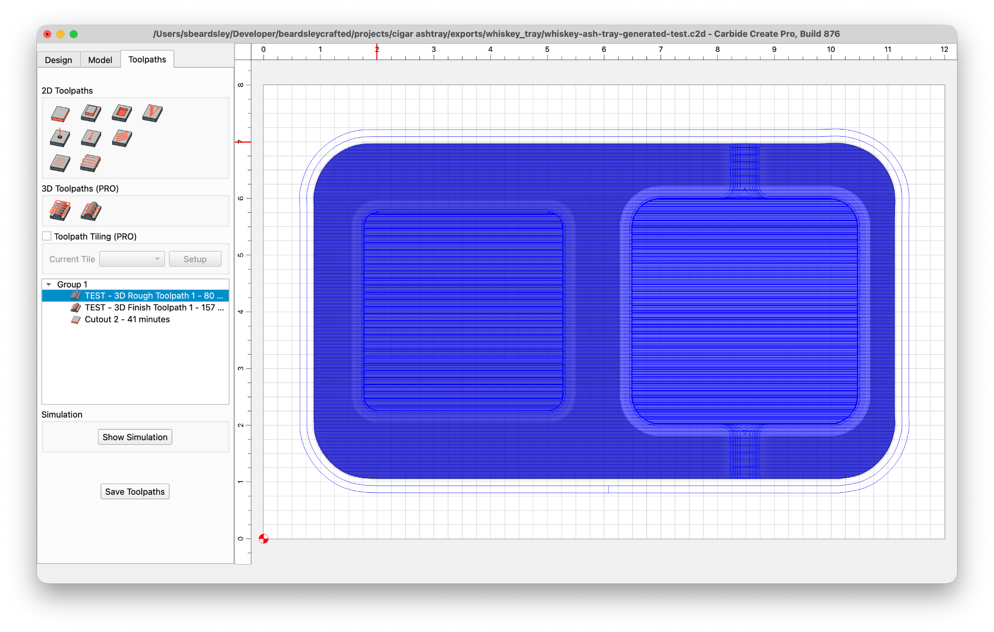
Toolpaths generated in Carbide Create from the imported design.
The simulation reached completion and showed the pockets, cigar rests, and outer shape cut into the simulated stock. Carbide Motion is the downstream part of my workflow for sending the resulting G-code to the machine. This experiment's record ends at the Carbide Create simulation.
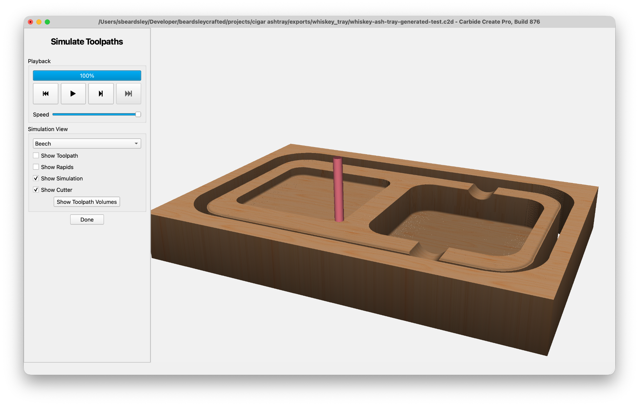
The simulation at 100% playback. This is a preview of material removal.
What remains open
I still need physical evidence for fit and surface quality. The liner is also explicitly a conceptual metal cup in the code, with its manufacturing method still to be chosen. Having a separate STL for it doesn't settle that question.
For this small experiment, generating code turned out to be a useful way to get AI involved in a dimensioned design. I got geometry I could inspect in VS Code, exports for printing and CNC, and a model I could take through CAM simulation. Whether the physical part behaves as intended is a separate test.
Evidence: the VS Code/build123d screenshot and Carbide Create model, toolpath, and completed simulation screenshots. This entry records the design and CAM stage.